
| INTRODUCTION | ACTUAL SET UP | COMPARISON | PROJECT SET UP |
| INSTRUCTION | CIRCUIT DETAILS | HARDWARE | CONCLUSION |
|
CIRCUIT DETAILS |
CIRCUIT REQUIREMENTS:
The hardware circuit requirements details consists of
6.1) Programmic Circuit Board
6.1.2)Poteniometer
6.1.3)Soleniod Relays
6.1.4)LCD Display
6.1 Programmic Circuit Board
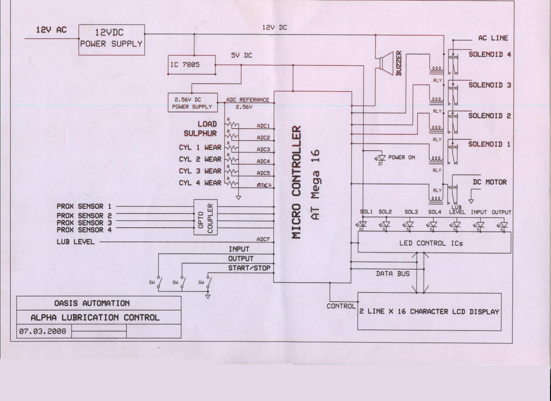
Figure 6.1: Programmic Circuit Board
6.1.2 POTENIOMETER
A potentiometer is constructed using a flat semi- circular graphite resistive element, with a sliding contact (wiper). The wiper is connected through another sliding contact to the third terminal. On panel pots, the wiper is usually the centre terminal. ‘Multiturn’ potentiometers where the resistor element may be helical and the wiper may move 10,20 or more complete revolutions. Besides graphite, other materials may be used to make the resistive element. These may be resistance wire, or carbon particles in plastic, or a ceramic/ metal mixture called cermet.
One form of rotary potentiometer is called a string pot. It is a multi-turn potentiometer with an attached reel of wire turning against a spring. It is convenient for measuring movement and therefore acts as a position transducer.

Figure 6.2: Poteniometer - Specification
6.1.3 SOLENIOD RELAYS
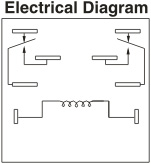
Figure 6.3: Sugar Cubed Soleniod Relays
SPECIFICATION
Configuration – 2 CO (2 Form C)
2 NO (2 Form A)
Contact rating – 30 A at 240 v AC/ 24v DC
(Resistive) ( Higher AC Voltage Contact rating Model also available)
Contact Resistance -100 mohm max (initial)
Contact Material - Silver Alloy
General Performance
Operate time - 30 msec max
Fast Switching version - 10 msec max
Release time - 10 msec max
Life Expectancy
Electrical - 5x10⁴ Operations at rated load
Mechanical - 106 Operations
Dielectric Strength
Between Open Contacts -1000 VAC
Between Coil & Contact - 2000 VAC
Between Any terminal & earth - 2000 VAC
Insulation Resistance -1000 Mohm min @ 500 VDC, 25°C & RH 50
Temp. Range - -40°C to + 70°C
Mounting - Chassis mounting
6.1.4 DISPLAY UNIT CIRCUIT
Figure 6.4: LCD CIRCUIT
Circuit Description
The LCD panel's Enable and Register Select is connected to the Control Port. The Control Port is an open collector / open drain output.. Therefore by incorporating the two 10K external pull up resistors, the circuit is more portable for a wider range of computers, some of which may have no internal pull up resistors.
Therefore we hard wire the R/W line of the LCD panel, into write mode. This will cause no bus conflicts on the data lines. The 10k Potentiometer controls the contrast of the LCD panel. Nothing fancy here. As with all the examples, I've left the power supply out. You can use a bench power supply set to 5v or use a onboard +5 regulator. Remember a few de-coupling capacitors, especially if you have trouble with the circuit working properly.
The 2 line x 16 character LCD modules are available from a wide range of manufacturers and should all be compatible with the HD44780.
|
POWER SUPPLY |
6.2.1 Introduction:
All the electronic components starting from diode to Intel IC’s only work with a DC supply ranging from +5V to +12V. We are utilizing for the same, the cheapest and commonly available energy source of 230V-50Hz and stepping down, rectifying, filtering and regulating the voltage.
6.2.2 Step down transformer:
![]()
Figure 6.5:Transformer
When AC is applied to the primary winding of the power transformer, it can either be stepped down or stepped up depending on the value of DC needed. In our circuit the transformer of 230V/12-0-12V is used to perform the step down operation where a 230V AC appears as 12V AC across the secondary winding. Apart from stepping down voltages, it gives isolation between the power source and power supply circuitries.
6.2.3 Rectifier unit:
In the power supply unit, rectification is normally achieved using a solid state diode. Diode has the property that will let the electron flow easily in one direction at proper biasing condition. As AC is applied to the diode, electrons only flow when the anode and cathode is negative. Reversing the polarity of voltage will not permit electron flow.
A commonly used circuit for supplying large amounts of DC power is the bridge rectifier. A bridge rectifier of four diodes (4 x IN4007) are used to achieve full wave rectification. Two diodes will conduct during the negative cycle and the other two will conduct during the positive half cycle, and only one diode conducts. At the same time one of the other two diodes conducts for the negative voltage that is applied from the bottom winding due to the forward bias for that diode. In this circuit due to positive half cycle D1 & D2 will conduct to give 0.8V pulsating DC. The DC output has a ripple frequency of 100Hz. Since each alteration produces a resulting output pulse, frequency = 2 x 50 Hz. The output obtained is not a pure DC and therefore filtration has to be done.
The DC voltage appearing across the output terminals of the bridge rectifier will be somewhat less than 90% of the applied rms value. Normally one alteration of the input voltage will reverse the polarities. Opposite ends of the transformer will therefore always be 180 degree out of phase with each other. For a positive cycle, two diodes are connected to the positive voltage at the top winding.
6.2.4 Filtering circuit:
Filter circuits which is usually capacitor acting as a surge arrester always follow the rectifier unit. This capacitor is also called as a decoupling capacitor or a bypassing capacitor, is used not only to ‘short’ the ripple with frequency of 120Hz to ground but also to leave the frequency of the DC to appear at the output. A load resistor R1 is connected so that a reference to the ground is maintained. C1, R1 is for bypassing ripples. C2, R2 is used as a low pass filter, i.e. it passes only low frequency signals and bypasses high frequency signals. The load resistor should be 1% to 2.5% of the load.
1000mf/25V : for the reduction of ripples from the pulsating
10mf/25V : for maintaining the stability of the voltage at the load side.
0.1mf : for bypassing the high frequency disturbances
6.2.5 Voltage regulator:
The voltage regulators play an important role in any power supply unit. The primary purpose of a regulator is to aid the rectifier and filter circuit in providing a constant DC voltage to the device. Power supplies without regulators have an inherent problem of changing DC voltage values due to variations in the load or due to fluctuations in the AC linear voltage. With a regulator connected to the DC output, the voltage can be maintained within a close tolerant region of the desired output. IC7812 and 7912 is used in this project for providing +12V and 12V DC supply.