
| INTRODUCTION | ACTUAL SET UP | COMPARISON | PROJECT SET UP |
| INSTRUCTION | CIRCUIT DETAILS | HARDWARE | CONCLUSION |
|
PROJECT EXPERIMENTAL SET UP |
4.1 SYSTEM EXPLANATION
This system is designed for four-cylinder engine. Electronic control unit or Micro controller plays the vital role in regulating lube oil injection timing. Lube oil is injected to each liner unit by means of small pressurized pump. Lube oil to the quill points is injected accurately at required timing by giving signal to the appropriate solenoid valve. The ON / OFF signal to the solenoid valve from the micro controller is determined by the variations in the engine load, cylinder wear of engine and sulphur percentage in the fuel.
Engine load variations , sulphur percentage and cylinder wear in the fuel are given as input to the micro controller through the panel board. DC servomotor with 30 rpm used as reference motor, from where the degree for lube injection timing is calculated. The current status of the operations is monitored and continuously displayed in LCD.
The low level of lube oil is automatically activated by float sensor and alarm is activated out by visual and audible alarms.
Thus the lube oil amount injected is proportional to the engine load and sulphur content which saves a larger amount of annual cylinder oil consumptions.
4.2 Timing Diagram
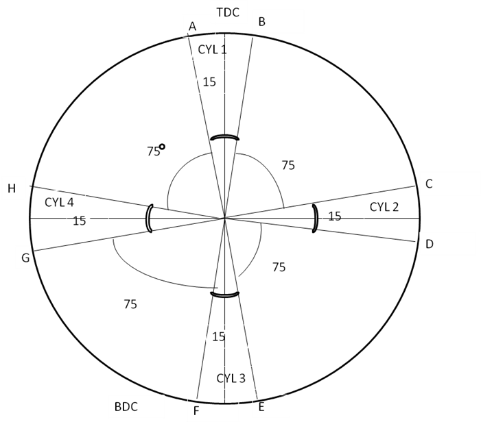
For ease of calculations timing diagram of four cylinder engine is discussed in this project. The timing for lube injection starts when the quill points crosses second and third rings of piston and it is approximately 15º - 20 º before TDC and ends at 10 º - 5 º after TDC. Let the firing order for this engine is 1-4-2-3. The difference in firing angle between four cylinders is 90 º.
Timing diagram for four-cylinder engine is shown above
AB – Lube oil injection timing of cylinder 1
CD – Lube oil injection timing of cylinder 2
EF – Lube oil injection timing of cylinder 3
GH – Lube oil injection timing of cylinder 4
BC, DE ,FG and HA are idle periods.
AB = CD = EF =GH = 15º (ON time)
BC = DE = FG =HA = 75º (OFF time)
|
EXPERIMENTAL SET UP |
LAYOUT OF THE SYSTEM
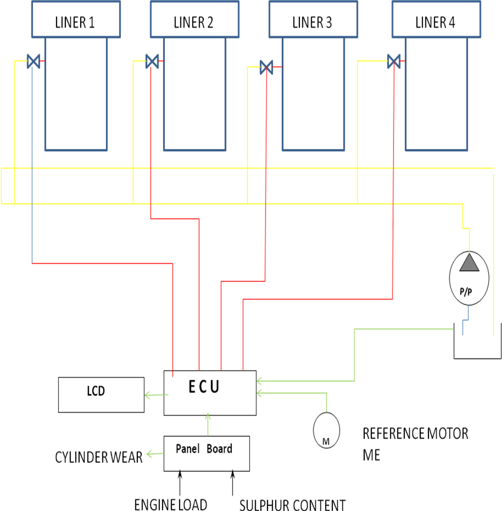
Figure 4.4: Layout of the System
4.3 Mechanical setup
The mechanical part of the system comprises of
The main frame
Cylinder liners
Fly wheel
Calibrated collecting jars
Stand for each jar
4.3.1 Mainframe
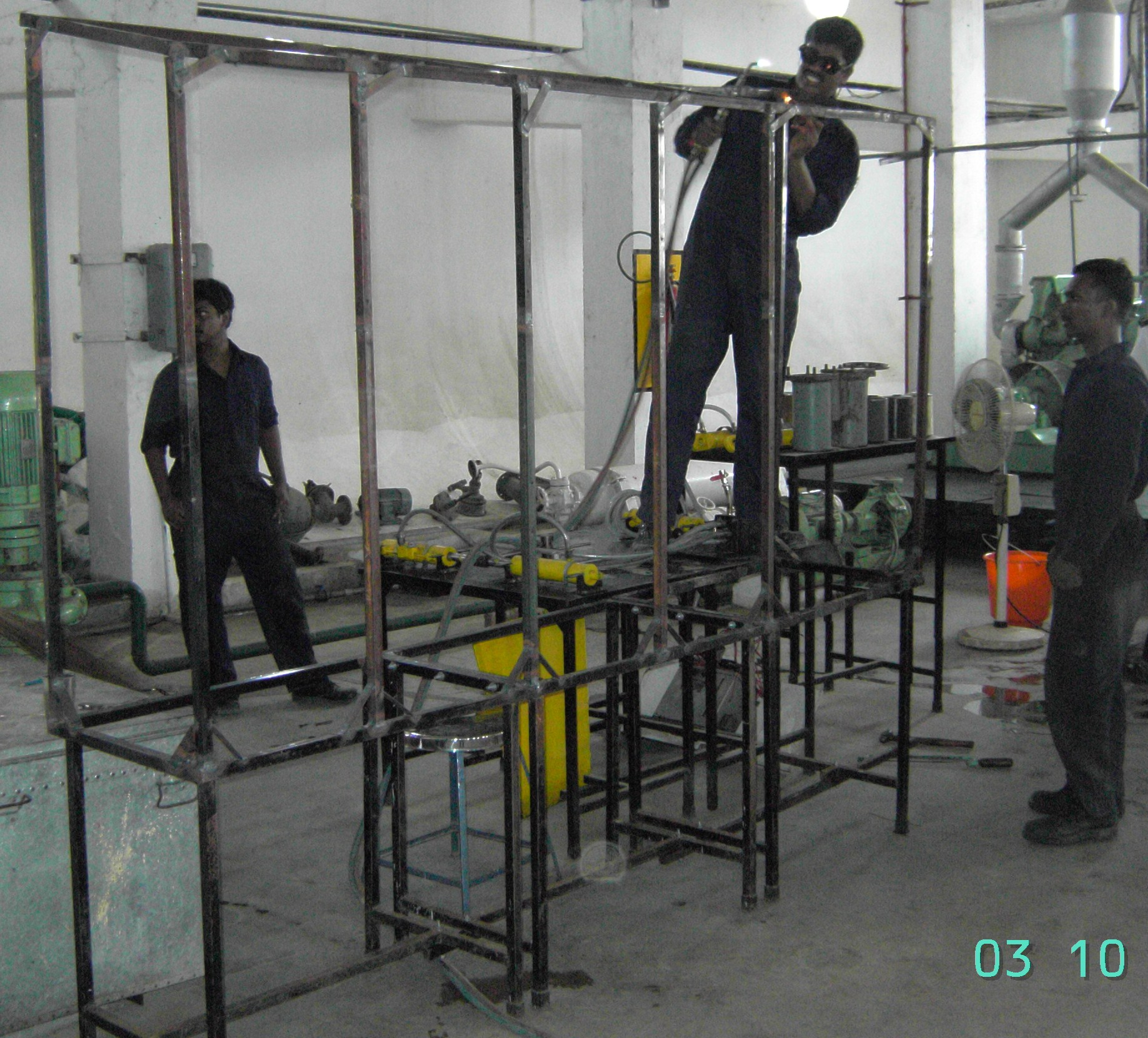
The MAIN FRAME is 8x2x7 feet, of which the first 3 feet from the bottom is used for tank arrangements. The frame is fabricated from scraps. These scraps were cut, ground, welded and put in shape. Stiffeners were welded to give additional strength. These frames are fitted on all sides with plywood sheets of 10mm thickness. The top of the frame is given 15 degree inclination. On which 2 bulbs of 25 watts, 230v AC are fitted. The front end of the frame is fitted with an ‘E’ channel to enable acrylite doors with rollers to slide through , Chalk powder mixed with turpentine are used to level the surface of the plywood.
Figure 4.5 Fabrication of main frame
4.3.2 Cylinder liner
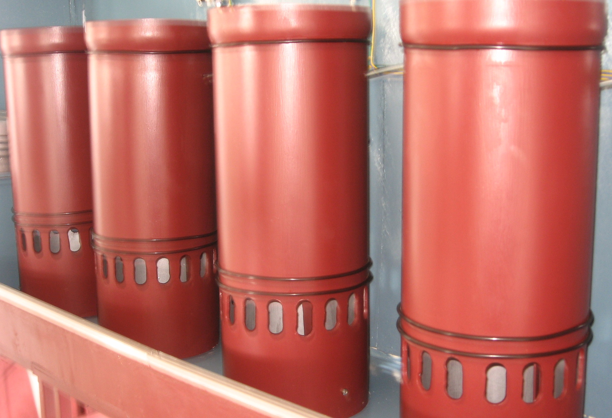
The system has a total of 5 liners, of which one is a cut section. Each liner is 650mm high. Each liner has 17 ports of length 60mm and width 30mm. The port starts from a length of 150mm from the bottom of the liner. It has an outer diameter of 260mm and 240mm of inner diameter. The liners are fabricated from PVC (Poly Vinyl Chloride). The upper end of the cylinder is heated and expanded to a diameter of 280mm.
Figure 4.6: Cylinder liner
4.3.3 Flywheel
 A flywheel is fitted to the right end of the system of diameter 320mm and 30mm
thickness. It is manufactured using PVC and is fitted with a motor. The primary
rpm of the motor is 300 and is reduced to 30 using reduction gears. Electrical
connection is drawn from the main supply. It has a pointer made of steel for
sensing purposes. The gears are made of wood and are carefully made and brought
to shape.
A flywheel is fitted to the right end of the system of diameter 320mm and 30mm
thickness. It is manufactured using PVC and is fitted with a motor. The primary
rpm of the motor is 300 and is reduced to 30 using reduction gears. Electrical
connection is drawn from the main supply. It has a pointer made of steel for
sensing purposes. The gears are made of wood and are carefully made and brought
to shape.
Figure 4.7: Fly wheel
4.3.4 Measuring Beakers

Each liner has a calibrated collecting jar of maximum 250ml capacity. These jars are placed on a stand fitted to the main frame. These jars collect the lubricant injected into the cylinder. The amount of oil injected can be measured, which differs for each cylinder. These beakers can be removed and emptied before each running of the system.
Figure 4.8: Measuring Jar
4.4 Electrical set up
Electrical setup of the system comprises of
4 Nos 230v AC Solenoid valve
4 Nos proximity sensors – 3mm sensing range
1 No 30rpm 24v dc motor
Float switch
4.4.1 Solenoid valve
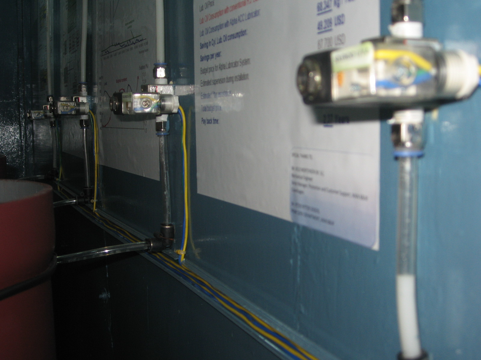
4 solenoid valves are used. The valve is rated to 230v ac. The phase supply to the solenoid valve is given individually from the integrated circuit board. The neutral wires are connected in parallel and connected to the switch board. The earth is connected in series. These solenoid valves are fitted to the main frame between the main line and the quill to each cylinder.
Figure 4.9: Solenoid valve Arrangement
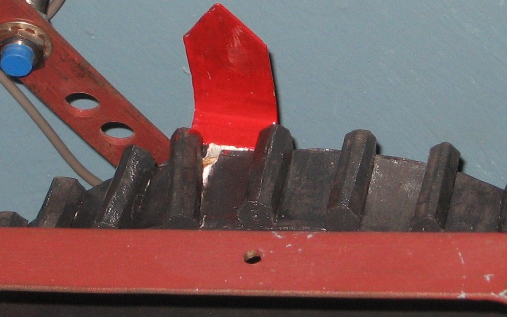
4.4.2 Proximity Switch

The proximity switches used are of NPN sink type. Four sensors are used, each sensor for a single unit. The sensing range of the sensor is 3mm. The output signal is given to the integrated circuit board. The proximity sensor is placed at a phase difference of 90 degree around the flywheel. These sensors are put in place by a stand fabricated with holes drilled into it.
Figure 4.10: Proximity Switch
4.4.3 DC motor
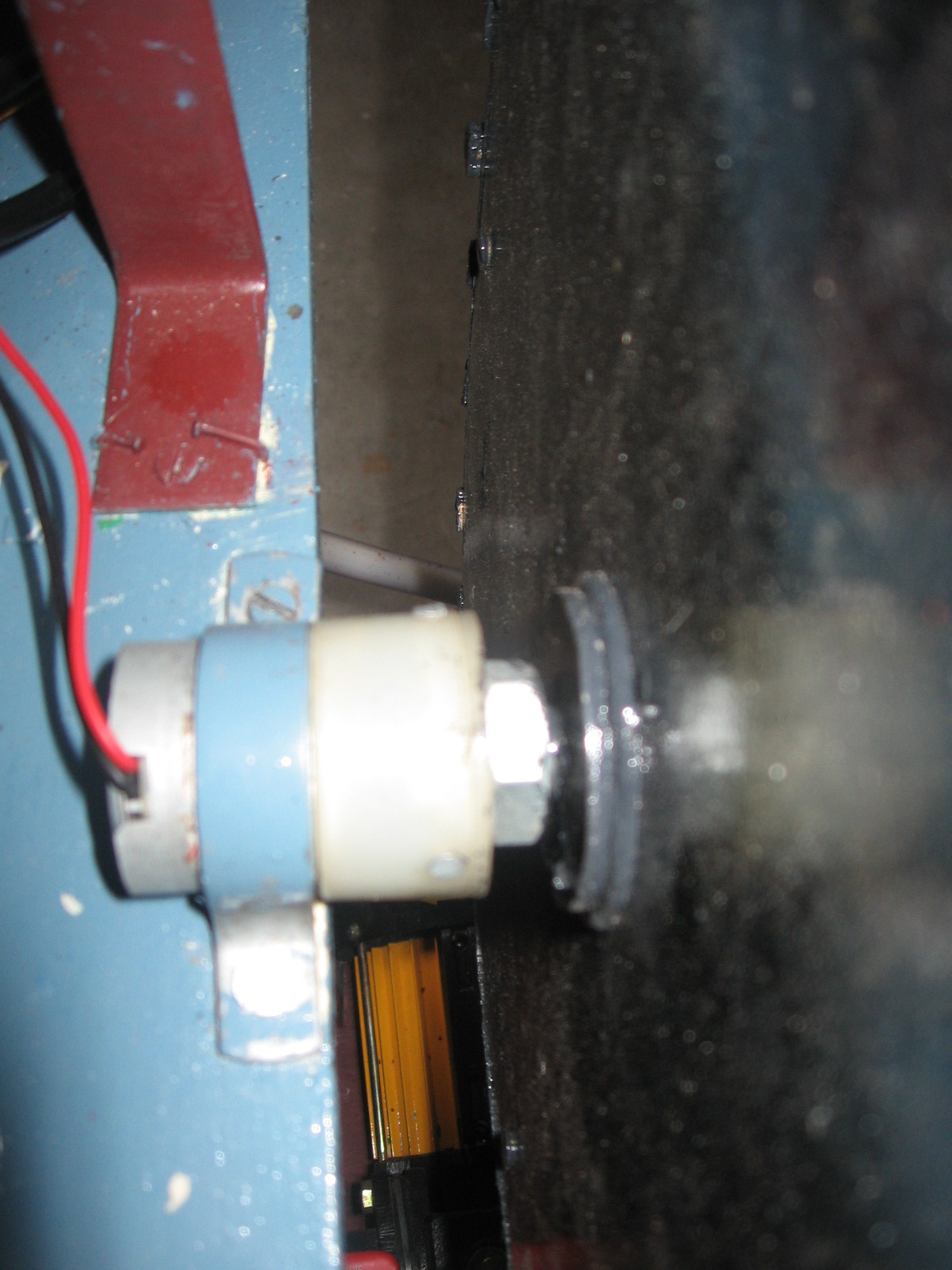
The dc motor used with the flywheel has a rating of 24v dc. The motor has an rpm of 3000, which is brought down to 30 rpm. This is achieved by using internal reduction gearing to reduce the output. The flywheel motor gets supply from the micro controller unit. The system starts the sensing after the dc motor starts running.
Figure 4.11: DC Motor
4.4.4Float switch
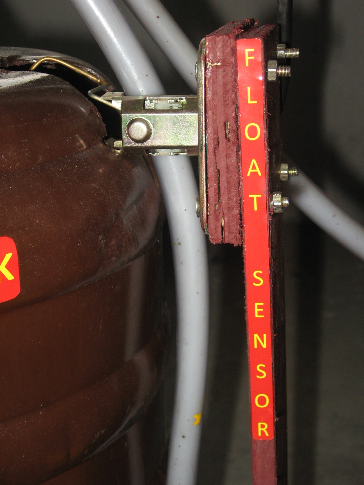
A float switch is used to sense the level of lube oil in the service tank. The switch is connected to the integrated circuit board. It has a maximum range of 5mm. it is bolted to a stand made of wood which in turn is fitted to the base plate. In case of a low level alarm it activates an audio visual alarm.
Figure 4.12: Float Sensor