
| INTRODUCTION | ACTUAL SET UP | COMPARISON | PROJECT SET UP |
| INSTRUCTION | CIRCUIT DETAILS | HARDWARE | CONCLUSION |
4.5 Hydraulic set up
Hydraulic system consists of
1. 2 tanks – one for storage and other for service
2. 5 ball valves
3. Hoses
4. 7 T piece
5. Pump
6. Nipple
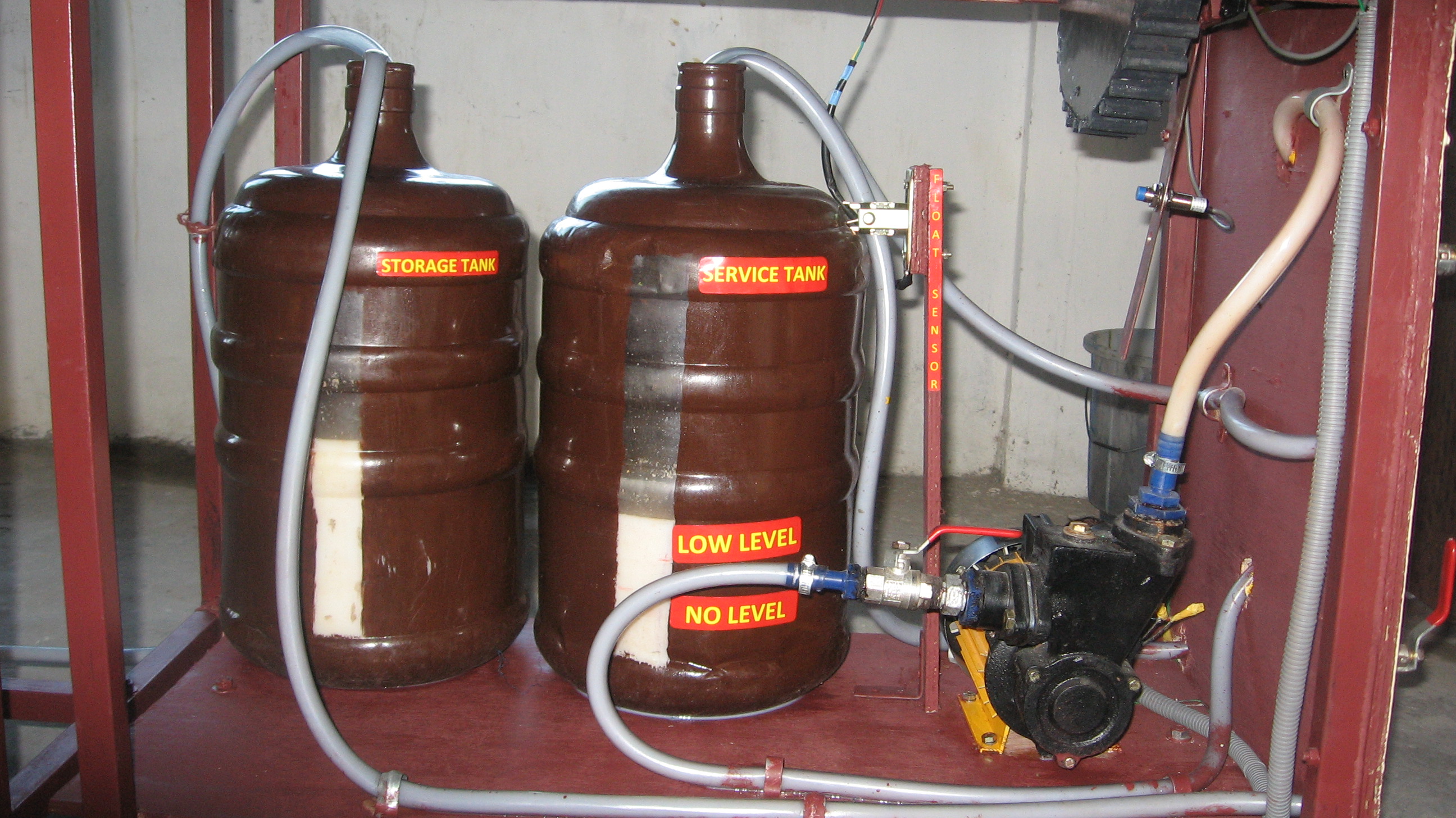
The service and storage tank are of 20 liters capacity. A 1/2hp pump is used for taking suction from the service tank and storage tank .when the pump is switched on suction is taken from the service tank and circulated through the system which finally drains into the storage tank, when the service tank level comes down the suction is taken from the storage tank and drained into the service tank and the cycle continues. This is achieved by operation of change over valve.
4.6 Electronics set up
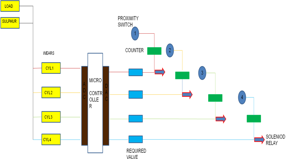
Figure 4.15: Logic for Micro Controller
The logic behind the integrated circuit board is that engine load value or signal and fuel sulphur content signal is combined with the liner wear of each cylinder and given to the microprocessor. The microprocessor processes the signal and gives an output signal which is the required value for each cylinder. The required value for each cylinder varies according to the liner wear of the cylinder, the load and sulphur content is constant for all the units. The proximity sensor senses the count of the flywheel revolution using a counter. When the signal from the counter matches with the signal required by each unit a signal is passed to the solenoid valve for operation. Once the signal is processed the counter resets and starts counting from start.
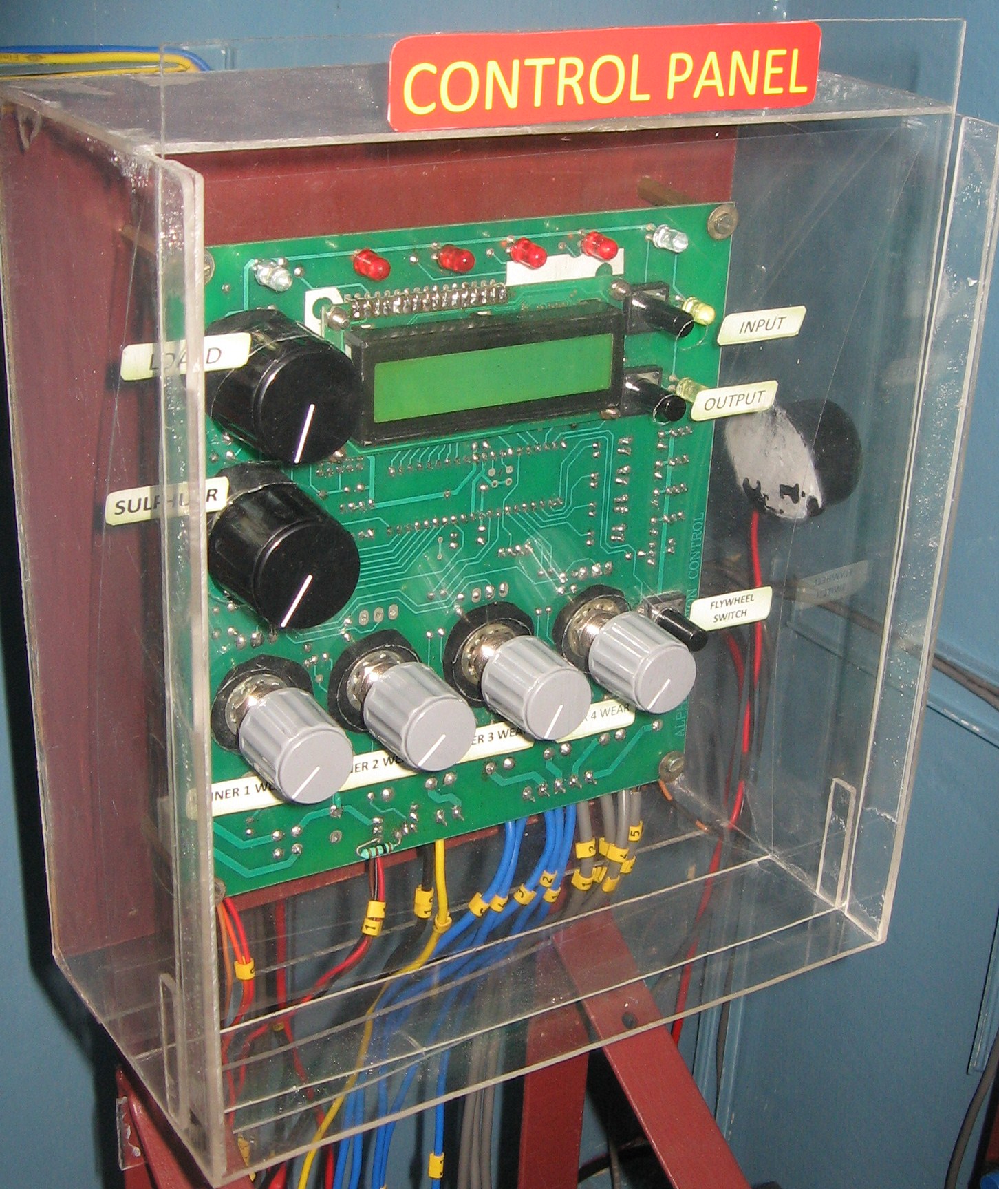
Figure 4.16: Micro Controller
A 16 digital LCD display is fixed in the integrated circuit board.
Two buttons are provided to change the display mode from output to input. By pressing the input signal button repeatedly the unit display can be changed and the values for each cylinder unit can be entered. By pressing the output signal button repeatedly the output of each unit is displayed. The input display consists of load , sulphur content and cylinder wear rate for the unit. The output display consists of the cylinder unit, the required value and the counted value from the sensor for that unit.
Each solenoid valve opening can be monitored by LED light visually. A buzzer is fitted along with a LED to give an audio visual alarm for LOW LEVEL and NO LEVEL in the lube oil tank. When no level is reached in the lube oil tank, the FLYWHEEL STOPS, there by stopping the lube oil injection.